How to use a breadboard
The plastic board with all the holes — and the hidden pattern inside it.
In 10 seconds
- • Short rows are connected; the middle gap is not.
- • Long side rails carry power and ground.
- • Neat wiring makes bugs easy to spot.
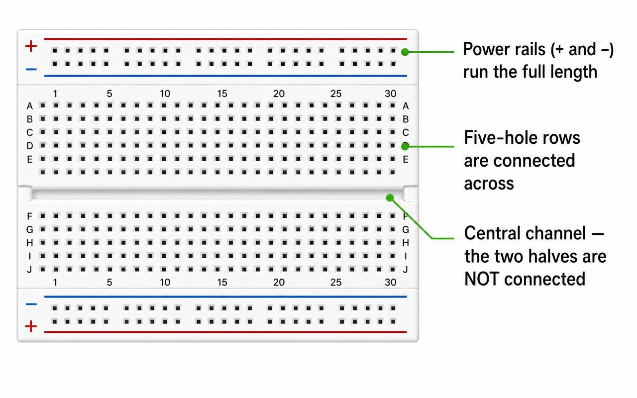
A breadboard lets you build a real circuit without soldering anything. You push component legs into holes, and metal clips hidden underneath grip them and connect them together. When the project is finished, or when you made a mistake, you simply pull everything out and start again. It is the electronics equivalent of building with LEGO instead of glue.
The hidden pattern
The holes are not all connected randomly — there is a strict pattern, and understanding it is the whole skill.
- The middle section is divided into short rows of five holes. All five holes in a row are joined together. So if you put an LED leg in one hole and a wire in another hole of the same row, they are connected.
- The channel down the centre splits the board into two halves that are not connected. This gap exists so that chips can straddle it with their legs on separate rows.
- The long rails at the edges, marked with red + and blue − lines, run the whole length of the board. These are for power and ground, so you can grab 5V or GND from anywhere.
Notice the direction: the middle rows run across the board in short groups, while the outer rails run along it. Mixing these two up is behind an enormous share of circuits that "should work but don't".
Habits of a tidy builder
A messy breadboard is genuinely harder to debug than messy code, because you cannot search it. A few habits make a huge difference:
- Always run red from 5V to the + rail and black from GND to the − rail first, before anything else.
- Keep wires short and flat against the board instead of arching over it.
- Use colour meaningfully: red for power, black for ground, other colours for signals.
- Build one section at a time and test it before adding the next.
Common breadboard mistakes
Nine times out of ten the fault is mechanical, not electrical. These are the ones that catch almost everybody:
- Both legs of a component in the same five-hole row. That row is one connection, so you have shorted the component out. Straddle two different rows instead.
- Wiring across the central channel by accident. Row 12 on the top half and row 12 on the bottom half are separate connections, not one.
- Forgetting to link the two power rails. On most boards the left and right (or top and bottom) rails are not joined — add a short jumper if you need power on both.
- A rail that is split in the middle. Some boards break the long rails halfway along, shown by a gap in the red or blue line. Bridge it with a jumper.
- Legs not pushed fully in. A leg resting on top of a hole looks connected but is not. Push until it sits firmly.
- Missing a common ground. Every part of the circuit, including any separate battery pack, must share the same − rail as the Arduino.
- A tired old board. Well-used breadboards develop loose holes; if one spot behaves oddly, move the circuit over a few rows.
Moving on from the breadboard
Breadboards are for experimenting. Once a project works and you want to keep it forever, transfer it to a soldered prototype board, or design a small circuit board of your own. But every one of those permanent projects started life exactly where yours is now: pushed into a piece of white plastic full of holes.
Questions people ask
- How does a breadboard work?
- Metal clips hidden under the plastic grip the legs you push into the holes and join them together. Each short row of five holes in the middle is one connection, and the long rails down the edges are separate connections for power and ground — so you can build a circuit without soldering anything.
- Which holes on a breadboard are connected?
- In the middle section, the five holes in each short row are connected across the board. The long rails at the top and bottom edges, marked + and −, are connected along the whole length. The channel down the centre separates the two halves — they are not connected to each other.
- How do I read a breadboard diagram?
- Follow each wire from one hole to another and remember that touching the same row means being electrically joined. Red lines usually mean 5V, black or blue mean ground, and the numbered columns and lettered rows in the diagram match the printing on a real board so you can copy hole for hole.
- Why is my breadboard circuit not working?
- Check for the classics first: both legs of a component in the same five-hole row, a wire crossing the central channel that you assumed was connected, a leg not pushed fully in, or a power rail that is split halfway along the board and needs a jumper.
- Do I need a resistor on a breadboard?
- Not for the board itself, but every LED you connect to a 5V Arduino pin needs a current-limiting resistor — 220 Ω is a safe default. Without it the LED draws too much current and can damage itself or the pin.
- What do the + and − rails on a breadboard do?
- They carry power around the board. Run a red wire from the Arduino 5V pin to the + rail and a black wire from GND to the − rail, and every part of your circuit can grab power and ground from the nearest hole.
Quick quiz: Breadboards
3 questions to check it stuck.
Next lesson
🎨 Resistors
Ready to try it for real?
Pick a project and ask a parent, teacher, or trusted adult to check the parts and power before you build. Buying hardware is optional and at your own cost.
Explore projects